
talc processing flow diagram manufacturer Grasping strong production capability, advanced research strength and excellent service, Shanghai talc processing flow diagram supplier create the value and bring values to all of customers.
 WhatsApp)
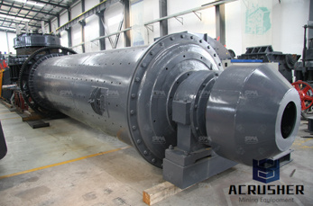
Talc Processing, and the corresponding background memorandum for the section. Following the previous industry review of the draft ... would also appreciate specific comments on the process description and process flow diagram presented in the enclosed draft AP42 section. Enclosed is a copy . of . the revised draft Section,
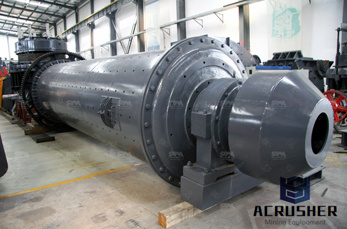
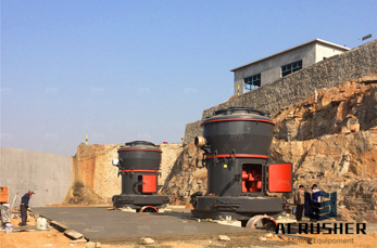
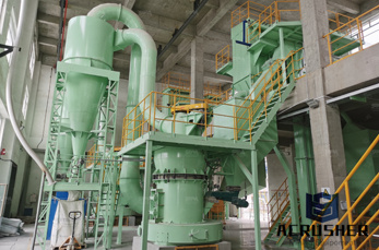
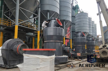
Mining operations usually consist of conventional drilling and blasting methods. Figure 21 is a process flow diagram for a typical domestic talc plant. Talc ore generally is hauled to the plant by truck from a nearby mine. The ore is crushed, typically in a jaw crusher, and screened. The coarse (oversize) material then is returned to the crusher.
The Data Processing Flow Diagram for PowerPoint presents a log data capture and processing workflow. This process flow diagram explains log management in distributed web architectures. The architecture model extracts log from transactions systems built in different architectures.
Flowchart Maker and Online Diagram Software. (formerly ) is free online diagram software. You can use it as a flowchart maker, network diagram software, to create UML online, as an ER diagram tool, to design database schema, to build BPMN online, as a circuit diagram maker, and more. can import .vsdx, Gliffy™ and Lucidchart™ files .
Mining and Processing of NonMetallic Minerals September 2014 iii List of figures and tables Figure 1 – Basic Process Flow Diagram for Perlite Manufacturing 3 Figure 2 – Process Flow Diagram for Feldspar Processes 4 Figure 3 – Flow Diagram for Phosphate Rock Processing 5 Figure 4 – Process Flow Diagram for Kaolin Mining and Dry Processing 6
Early Hematite Concentration Process Flow Diagram. Recent Hematite Concentration Process. In recent years, Hematite Concentration Process has made great progress, and its main Hematite Concentration Process are: the electromagnetic pulsating high gradient magnetic separator, represented by strong magnetic Hematite Concentration Process and to ...
flow distribution and absorbs packing stresses, reducing the tendency for brittleness. Gate location Generally, gates should be located so that the melt flow is from thick to thin sections. The other major consideration is to create as balanced a cavity filling pattern as possible for optimum control of differential shrinkage (warpage).
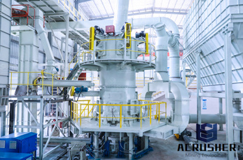
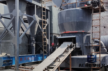
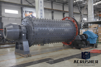
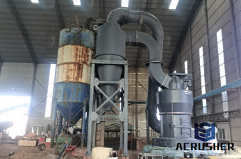
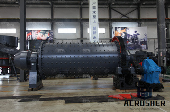
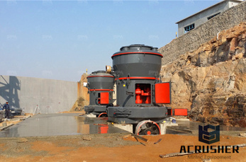
milling machine for talc fine processing Talc rocks are excavated at the mine and are delivered to the warehouse at theTo obtain fine talc the talc cake goes through a jet milling process, resulting in.
Talc is a clay mineral, composed of hydrated magnesium silicate with the chemical formula Mg 3 Si 4 O 10 (OH) in powdered form, often combined with corn starch, is used as baby mineral is used as a thickening agent and lubricant; is an ingredient in ceramics, paint, and roofing material; and is a main ingredient in many cosmetics. It occurs as foliated to fibrous masses, and ...
Mar 15, 2013· Cement grinding mill flow diagram,Crushing Process,Mining . cement packing plant layout diagram – . talc process flow diagram. cement industry process flow. . cement manufacturing collection process . »More detailed
The workflow diagram, or flowchart, was first created and introduced by Frank Gilbreth in 1921. At the time, it was referred to as a process flowchart, but after many years and many iterations, we have arrived at the modern workflow diagram.
The term talc refers both to the pure mineral and a wide variety of soft, talccontaining rocks that are mined and utilized for a variety of applications. Talc forms micalike flakes. Talc is the softest mineral on the Mohs hardness scale at 1 and can be easily cut and crushed. Talc .
How Does Talc Form? Talc is a mineral that is most often found in the metamorphic rocks of convergent plate forms from at least two processes. Most large talc deposits in the United States formed when heated waters carrying dissolved magnesium and silica reacted with dolomitic second process of talc formation occurred when heat and chemically .
Mar 01, 2015· Block Flow Process Diagram. This model will concentrate on a particular sector/area of a chemical plant. This would be a separate flow diagram that details what would have been present inside of one of the blocks in the plant diagram. These diagrams may be more or less complicated than the plant diagram but will focus on only a small sub ...
part 3d geometry aligns most of the flow paths in the direction of flow, then isotropic shrinkage would be less, so use (%) correction. all flow is in perpendicular to part length, then the shrinkage would be higher and correction value lower at (%)
Tensile stressstrain behavior coupled with fractography was used to investigate the weldline strength of an injection molded 40 w% talcfilled polypropylene. The relationship between processing conditions, microstructure, and tensile strength was established. Fracture surface of the weld line exhibited skincore morphology with different degrees of talc particle orientations .
Fig 1 Flow Chart for Production of EPDM by ZN Solution Process Fig 2 EPDM Raw Polymer Forms (friable bale and pellet) Fillers The main component used to reinforce the polymer is carbon black, which is one of the four forms of the element carbon. The types of carbon are, Diamond, a crystalline face, centered cube, Graphite a
Draw flowcharts and other diagrams with an online diagramming tool Online flowchart solution here! As a toprated diagramming tool, Visual Paradigm Online incorporates an intuitive draganddrop flowchart editor that allows you to create professional flowchart quickly and easily.
process flow diagram for talc processing . flow diagram for production of crushed hard rock,processing. Production Flow ChartFoodYou can use it as rock crusher or How to Make Perfume Talc talcum powder ...
If you''re introducing a new process at your workplace, or documenting an existing one, a process map template can help. A process flow chart template uses symbols and diagrams to depict complex processes from start to finish. Just enter your process data to the Excel flowchart template, then export to automatically create the shapes and connectors that visually tell the .
13 Process Flow Diagram for Talc Processing 24 Table 1 Emission Estimation Equations and Default Emission Factors for Various Operations at Coal Mines 38 2 Default Emission Factors for Various Operations at Mines 40 3 Estimated Control Factors for Various Operations at .
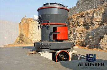
Figure is a process flow diagram for a typical domestic talc plant. Talc ore generally is hauled to the plant by truck from a nearby mine. The ore is crushed, typically in a jaw crusher, and screened. The coarse (oversize) material then is returned to the crusher. Rotary dryers may be used to dry the material.
Static tensile properties of talcfilled polypropylene have been studied in the past by several investigators [2–4]; however, its fatigue properties are not well known. Flowinduced filler orientation and weld lines are unavoidable facets of the injection molding process. Flowinduced filler orientation manifests in higher tensile prop
Apr 25, 2015· The recirculated flow was designed to ensure proper and continuous mixing of the suspension in the inlet tank. The flow rate of the recirculated water was controlled by a recirculating globe valve (V2). Download : Download fullsize image; Fig. 1. Process flow diagram of the filtration system with piping and instrumentation details.
WhatsApp)